|
|
This page is about passing on information that will be useful to some folks and probably old hat to others in the doing of repairs or improvements to your Lambretta. Contributions are welcome, subject to the disclaimer that Aunt jonbretta endorses nothing that she hasn't tried herself and found useful, and even that doesn't mean that a given idea applied will work for everyone.Common sense and experience reign supreme, and by sharing the latter and trying our best to apply the former things usually improve. Send contributions to jonbretta@jonbretta.net |
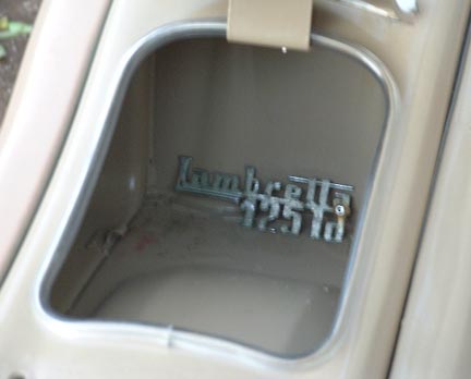
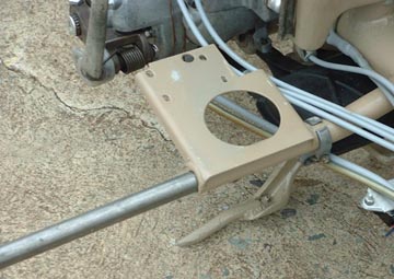
The first thing to do is put together a cable to operate the starter motor. I have no clue as to how long the cable is supposed to be. The MK III has the starter lever mounted on the left side of the glove box.The cable goes down from the lever and through holes in the glove box and then the legshield, and comes out inside the horn casting. It then basically joins the other cables down along the frame and to it's destination, the starter motor.
The MK II has a starter lever clamped to the handle bars. Your cable housing will probably be longer than the MK III version, but as long as you get the inner/outer differential right, it'll work.
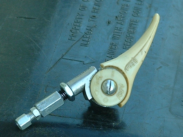
The cable assembly includes an adjuster set-up to give or take slack as necessary. This adjuster screws into the bottom of the starter lever. Since there are non-removable barrel ends on each end of the inner cable, the adjuster set-up must be included onto the upper end of the cable before the upper barrel is soldered on.
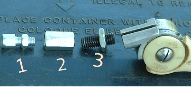
First you need to have all the parts.
1. For cable, you can use .050'' to .060'' cable. This is usually the guage for throttle or choke cables. Likely candidates are an extra-long throttle cable or maybe some bicycle gear-change cable. Start with at least 48'' or so.
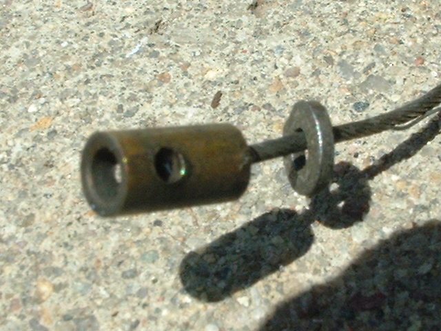
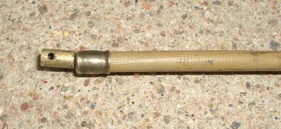
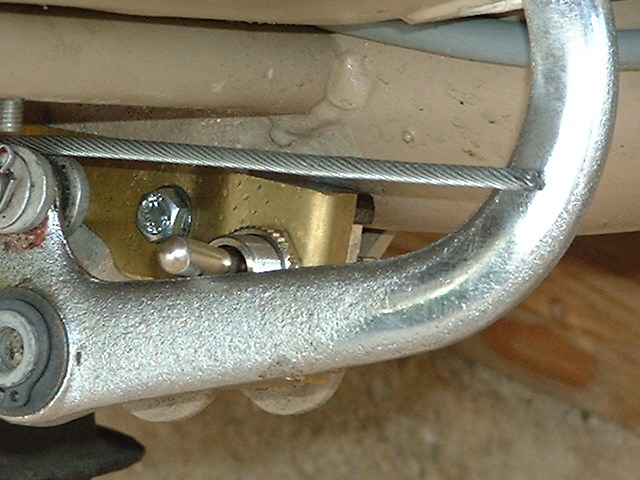
2.There's a barrel at the bottom end of the cable with a 2mm hole drilled through it cross-wise. This end slides into the starter switch box receptacle tube; a pin goes through the tube and the barrel's cross-drilling, attaching them together.
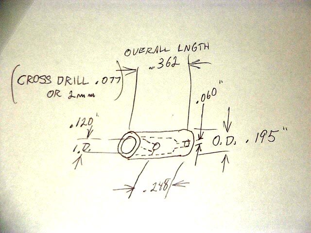
3.There's a barrel at the top end of the cable which is your basic Lambretta gear cable barrel, that is to say attached perpendicular to the cable. Here's a picture of a barrel made out of some 5/16'' brass threaded rod. I ground off the threads 'til it was down to .230'' or less in diameter. Then I cross drilled for the cable size, then countersinked it for when I flay out the strands before filling the countersink with solder.
See cable making procedure for some tips on soldering cable ends such as use silver solder, c-sink and flay strands, etc.
 After it was all drilled up I sawed it off to no longer than .330''.
4.Then there's the adjuster parts which I sort of made up out of stuff, having not the correct parts or even knowing what they look like.
5.Finally there's the housing. 42 1/2'' worked well for a housing length. If you don't include an adjuster assembly on your cable then make the housing 44''.
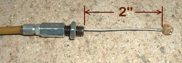
Next is the length differential between the inner and housing, This is the most important aspect of the cable. When the cable is completed, there should be 2 and 1/16th'' (I tried it before at an even 2'' but it was a little too tight) of exposed inner cable BETWEEN the upper barrel and the adjuster (or the housing end if you're not using an adjuster) when the whole assembled cable is lain out in a straight line, the housing and adjuster are all moved tight against the other barrel, and the adjuster(s) are adjusted in all the way; see pictures below.
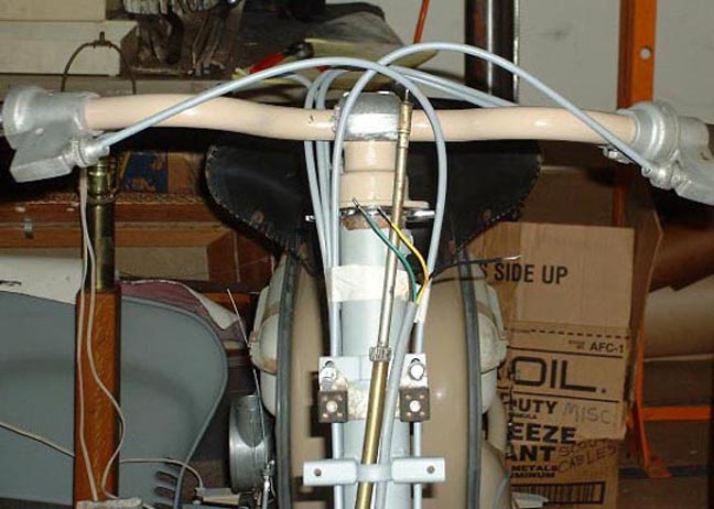
Here's the latest rendition of running the cable: Start feeding it at the top, through the rubber grommet on the left side of the toolbox, a few inches down from where the lever attaches. Feed it next through the rubber grommeted hole that goes through the center column of the legshield so that it comes out by the fork tube.
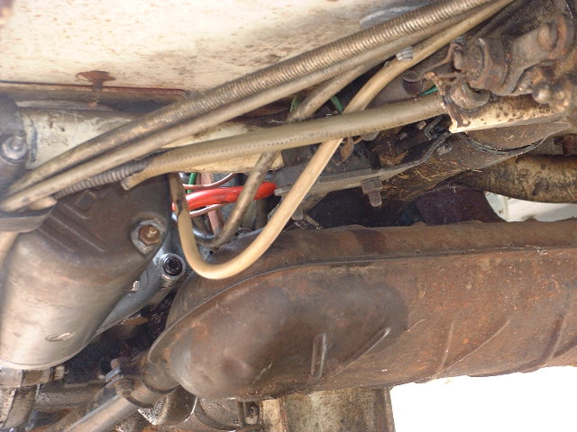
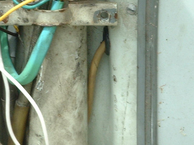 Run it BEHIND the fork tube and over to the right side of the tube and as you feed it along, guide it down along the other cables, where it might now take the top spot of all the cables. Pass it over the first crossmember and on back. Before the brake switch bracket, get a pick or hook or something and pull it out now to follow along around where the lower gear cable is.
Now set the starter motor up on a 4x4 facing back like how it's gonna go. Cut a 2'' piece of 1/2'' clear vinyl tubing for a boot and put it on the cable and slide it up out of the way for a minute. Now put the barrel cable end all the way up into the spring-loaded plunger on the starter switch box. Line up the crossbore of the cable end with that through the switch box and put in your pin.
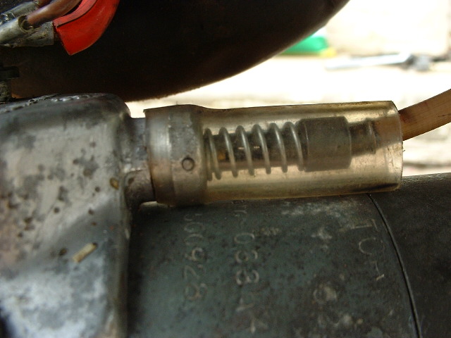 I used a piece of welding rod 'cause it's about the right hardness. It's got to be exactly as long as the switch box crossbore. (Not long enough, the box crossbore won't support it well, too long and you cant get the boot on or off easily). Now push on the vinyl boot over the switch box collar and it will retain the pin.
Now go ahead and mount up the starter motor. Put some heavy grease on the gears first. You should have a loop of excess cable hanging down. A word of caution here: Don't use too long an allen bolt at the lower rear location as the hole goes all the way through to the armature; if the bolt is too long it'll clamp right down on the arm. windings with possibly BAD results. Same goes for the two bolts or screws which hold on the switchbox. Too long and you'll lock up the arm. or wreck the windings. A good auto electric shop can rewind your arm. for $100-200 dollars. Anyway, you should have a loop of excess cable hanging down.
 If you don't the cable won't work BECAUSE; This Lambretta cable doesn't work like the others by pulling the inner, it works by pushing the outer, which pushes the switch box plunger, and it needs some extra length, or loop, to be able to travel.
It's like a reverse-pull front brake set-up. Trust me, I learned the hard way the first time when I didn't leave enough slack down there and it didn't work.
If you don't the cable won't work BECAUSE; This Lambretta cable doesn't work like the others by pulling the inner, it works by pushing the outer, which pushes the switch box plunger, and it needs some extra length, or loop, to be able to travel.
It's like a reverse-pull front brake set-up. Trust me, I learned the hard way the first time when I didn't leave enough slack down there and it didn't work.
Well I think that should be about it for that project.
My home made LD tools.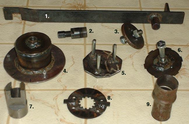
1. Flywheel holder. For all Lambrettas. Details on the jonbretta products page.
2. Flywheel puller. I didn't make this one, I bought it.
3. Rear hub puller. One set of holes is for LD, another set is for LI.
4. LD magneto flange puller. Screws onto flange after removing stator, big middle screw pushes on crankshaft.
5. LD clutch compressor. Compresses clutch against springs so that you can remove the clutch retaining circlip.
6. LD clutch bell puller. Made from a clutch metal (driving) disc, held within the bell by placing the circlip back in over it,
big middle screw pushes on mainshaft.
7. LD clutch hub holder. Machined from 1 1/2'' diameter steel rod. Keeps clutch from turning while you R&R clutch bell nut.
8. LD clutch collar holder. Made from a clutch cork (driven) disc. Locks collar with bell while you R&R clutch collar nut. One of those welded-on tangs actually should be a few inches long to brace against the muffler mounting stud lug on the front of the crankcase.
9. LD crankshaft seal set. Its use is described in the tech topix page, crank seal procedure article.
For a more informative and practical description about any of the items, email me.
Substitute MK III bullet taillight lens.
 A functional substitute LD bullet taillight lens can be had for a few bucks at the local camper and RV parts and supply store.
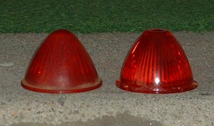
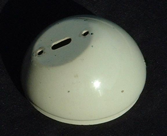
This picture shows the real and the camper lenses, in no particular order. The mounting diameter is identical to the original at 2.420''. The camper part may have little stand-off edges like the one I got did where the spring clip lies against it , those need to be filed off to allow the clip to go deep enough to expand back out inside the taillight chrome shell.
A functional substitute LD bullet taillight lens can be had for a few bucks at the local camper and RV parts and supply store.
This picture shows the real and the camper lenses, in no particular order. The mounting diameter is identical to the original at 2.420''. The camper part may have little stand-off edges like the one I got did where the spring clip lies against it , those need to be filed off to allow the clip to go deep enough to expand back out inside the taillight chrome shell.
Substitute MK III toolbox gasket.
 A functional substitute for the MK III toolbox door gasket can be made by getting some 3/16'' clear vinyl tubing and slotting it lengthwise. WARNING: This is a really dangerous thing to do. Wear gloves; if not chain mail then at least leather. Keep your face WELL AWAY from the job. Limit the force applied to cutting. Cut away from yourself. Have no part of you in the path if the cutting tool if it slips. I don't recommend anyone doing this.
Substitute MK III airhose.
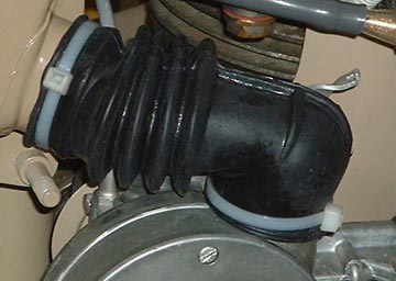 It's a Lambretta GP150/200 airhose. This piece is alot easier to find (at least from my usual sources) than the ''LD MK III'' airhose which people seem to be oftentimes out of. Also, what is sometimes sold as the MK III part is at the same time described to fit the Serveta Jet 200/150 Special. The Serveta part is long enough to get the Serveta job done but it's a chore to stuff all of that length into the LD application. The GP part works really well on at least this LD and I'm sure it will on yours.
It fits a shade loose on both ends when you put it on but it zipties/clamps down real well. It's not so loose that when you clamp down it puckers or buckles or anything, it just compresses down nice and even like. It's also a good length and when you sit on the scooter and the hose stretches, it has plenty of extension available. Referring to the picture, I could have put the ziptie joints around the back of the hose so it'd look better but I was so enthused about it that I didn't care, so I'll probably re-do them (DUH!!!).
<
An available LD exhaust gasket
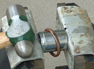 I finally got up the annoyedness at not knowing what to use for the exhaust gasket time after time enough to actually go do something about it. So me and my muffler went to the local multi-brand motorcycle dealership parts department and found someone who looked like he could find me the best thing thiy had to fill the bill (wasn't his name Bill? no, couldn't be.). Well find it he did, this is what it is; it's a Honda exhaust gasket, part no. 18291-MN4-920. It's a little oversize on the diameter, so just set it up like in the picture, and LIGHTLY, as it's very soft, peen down the outside all the way 'round. It only needs about .030'' reduction in diameter, so be careful. Drops right in, costs about $4.00, and you don't have to wait for the ''Lambretta LD'' one to arrive in the mail, you just go get one.
|
top 'o' page |
jonbretta home page | >
LD MK III cable housing installation |
|
|
This is about locating LD MK III cable housings onto the frame and to their destination components.This applies for the most part to MK IIs as well, except that from the horncasting up you have to make the cables comply with the rubber sheathing scheme which might require some minor change to the cable layout. MK I and II also have different locations for the rear brake and speedo cables as they pass the kickstart. I haven't looked at the MK II issue so I'm not sure. The MK I layout also will probably differ based on there being the single gear change cable, the rigid positioning of the gear and throttle cables from the handlebars, and maybe other things, I don't recall. To do this job the following the following things need be in place:
You now have 5 remaining. 3 have the smaller barrels on the inner and 2 have the larger barrels. Of the smaller barrels:
So much for that. |
|
|
Take all of the inners out (mark them if you need to) and set them aside.
The following 8 step program is in my recommended order. Click the pics to enlarge them. |
|
|
First put on the speedo cable. You must remove the threaded collar from the cable's rear end. It removes by popping of the spring C clip just outside of it. Then feed the rear end down through the fork tube's welded-on horncast bracket as
pictured in #5.
Run it down the right side of the frame over the R. brake cable support, under the brake switch, thru the cable guide, thru the
kickstart cable retainer(s) and back to the speedo drive as
shown in #4.
Put the screw collar back on and screw it onto the drive.
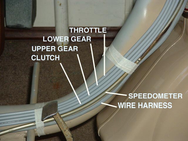
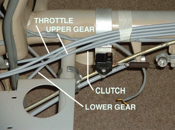
That's the speedo. Now lay the throttle, 2 gears, and clutch along the right side of the frame in the order shown with the harness at the bottom. Bind them to the frame with a zip tie just forward of the front crossmember. As shown, I used masking tape to place them, but a zip tie would work better. Make it tight enough to keep them from falling out of order, loose enough to allow you to slide them back and forth for exact placement. |
|
Bind the throttle, 2 gears, clutch, and harness to the frame again just behind the rear brake cable support.
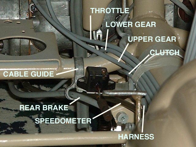
Now locate the rear brake cable. Put the rear brake ferrule in the cable support. From front to rear, put the cable under the brake switch, thru the cable guide, thru the kickstart cable retainer(s) and back to the it's cable adjuster on the tailshaft. Next, locate the lower gear cable. It goes over the brake switch bracket, over the frame crossmember, thru the kickstart cable retainer(s) and up to the selector box. With the speedo, rear brake and lower gear cables run, the rear view will look like picture #3. |
|
This is picture #3. |
|
Now for the rearward location of the throttle, clutch, and gear upper cables.
The throttle simply goes over the crossmember and up to the carburetor. The gear upper goes over the crossmember and straight to the selector box upper cable input. The clutch goes UNDER the crossmember and to the clutch cable support. Install the clutch ferrule in the support to locate the cable in place. |
|
Refer back to
picture #1.
Put on the next zip tie, half way up the diagonal section of the frame before the fork tube. Leave it just loose enough to slide the cables back and forth. Keep all the cables snug together and in the same order as in
picture #1. They'll stay in that order all the way up.
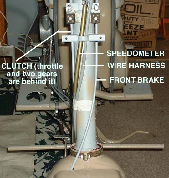
Continue the cables and harness up the fork tube. Put another zip tie around the 5 cables and the harness on the fork tube half way between the lower fork bearing and the horncast bracket After this new zip tie, the speedo and harness split off to to up through the horncast bracket, as shown in this picture. Continue the remaining throttle, 2 gears, and clutch cable up the right side of the fork tube and put another zip tie more loosely around them about 2 inches down from the upper fork bearing. Leaving that tie more loose will let you move the cables around to facilitate getting the legshield on. |
|
Now the handlebars. After this last tie, these 4 cables should all come up in order in front of the little notch on the right corner of the chrome bearing race holder beautyring thing. At this point, go get the little cable retaining ring which screws to the underside of the handlebar cover. Hold it in the position it should be in when screwed to the cover so that you know which way to put in on, and drop it over the 2 gears and throttle cables. Just leave it there; when it's time for it to install, it'll be there.
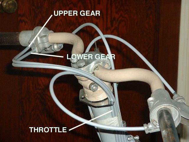
Now wrap the 2 gear cables around the back of the handlebars and over to the shifter. Gear lower cable goes in the lower hole, gear upper goes in the upper hole. The throttle goes back and to the right, and goes into the receptacle hole in the throttle control. The clutch cable stays in front of the handlebars, bends over to the left and goes into the hole for it in the clutch lever perch. |
|
You might now want to put into position the handlebar cover and attach the cable retainer ring to see how the cables sit behind and underneath the handlebars. Putting the throttle cable over or under the gear cables will result in different looks of how the cables sit. As long as the routing is smooth and graceful to facillitate cable operation, either way is OK. Also check that the front brake and clutch cables flow comfortably and smoothly under the cover.
Now for the front brake cable, which hasn't even been on the bike 'til now. You'll have to inch it along down thru the hole in the fender, thru the right fork leg welded-on guide, down to and thru the cast-in guide on top of the link enclosure area at the bottom of the fork, and finally into the front brake ferrule which installs in the hub back plate. The fender and upper fork guide holes are keywayed, which means that they will bite into the cable sheath and tear it up if they're forced or pulled, so just slowly and gently lift and help the cable along thru these and you won't regret the effort; you will if you don't take this care. |
|
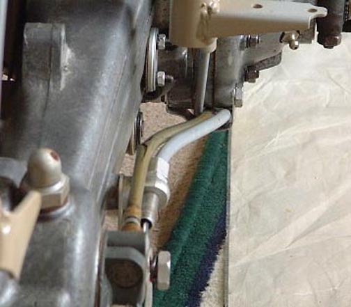
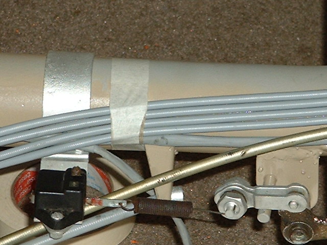
This picture refers to the clearance between the speedo cable and the brake light switch. The location of this portion of the speedo cable is controlled by the placements of the zip tie foreward of this point, and the cable guide on the crossmember to the rear. Since the zip tie is gonna stay where it is, you adjust the speedo cable clearance of the switch by where you tighten down the crossmember cable guide, slide it inboard until it runs safely under the switch and doesn't interfere with the switch spring operation Though it's a pain, wait until the legshield is on to finally position the switch bracket for height and on/off adjustment before you tighten it down. Picture #4 illustrates this nicely. |
|
Now install, hook-up and adjust all of the inners to all the controls. When they all seem to work well then tighten the zip ties
(with the exception of the top one) and cut off their excess length. Check operation again to see that you didn't overtighten any ties and bind any cables up.
Now you can put on the legshield. Put a washcloth over the top edge where it goes under the chrome lock ring so you don't scratch the paint. Put in the rear edge first, then as you begin to tuck the top front down, pull the four cables momentarily around the back of the fork tube to get them under and behind the legshield's fixing bracket before you try to spread it around the fork tube. When you're done, they should be behind that bracket and in front of the notch on the chrome. I think that's it. Not discussed here is the choke cable; go for it. Nor will be the installation and set-up of the inners, except to say to grease all inners as you install them in the housings. On the throttle cable, use a coating of transmission fluid instead of grease, and don't coat the first several inches so that if you want to solder a ball end on for the carburetor then it won't be contaminated with oil and wreck your solder job. |
|
Anyway having arrived at the torsionbar part of the game I thought I'd point some things about the assembly which might make the job go easier and/or better, especially for first-timers
Upon original assembly the bar was installed in the right position, and if you're going to take it apart for its first time since factory build you may want to put corresponding marks (punch marks would be good), one around the edge of one end of the bar, and the other mark on the circular face of the splined receptacle into which the bar installs. That way, when you re-install, you can put it right back where it originally was by just matching up the marks. If this wasn't done, then the following will help to get it put back together right.
The most important thing to know is about the bar itself. Specifically, the splines on the two ends of the bar are NOT THE SAME. The bigger end is .905'' around and has 22 splines. the smaller end is .860'' around and has 21 splines. That difference in splinecount of 1 means that you can install the torsion bar in any one of 21 different rotational orientations, with the goal being to find the one which results in your torsion arm being in the right position so that you can hook up the torsion arm, link, and motor lugs and arrive at the maximum ground clearance and suspension travel. Of course you could also set it up for special effects such as the lowrider look, combining such with 3.50 or 3.00 x 8 tyres, and a variety of accessories and paint job as would more typically be found on a lowrider automobile.
As a starting point I will work within the reference of the re-assembly of a scooter from the frame up with the following progress having been made
I'm building a LD 125 MK III these days. I'm painting it with spray can using Duplicolor brand ''CUMMINS BEIGE''
color engine paint because it was the only color spray can I could find that had approximately the right character of color for an LD, even if they never actually used that color. Colors like ''Wimbledon White'' or ''Ford Blue'' or Toothpaste Green are so TOTALLY WRONG for a Lambretta of the LD period but hey, knock yourself out ya know?
Not that I put my money where my mouth is, my Mk II is primer gray. I did put my money however into important parts to make this Mk III into a daily driver. Torsion bar set-up
With this arrangement the motor will rest at it's rearmost point of travel against the rear bumpstop.
Next, we'll discover which spline goes where (torsion bar adjustment). At this point we needn't bother with the final assembly items of grease, big thrust washer, torsion bar circlips or torsion boot.
 Right
Right 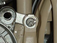
Once you find a spline orientation which puts the torsion arm as close as possible to the fender, make corresponding marks on the right end of the torsion bar and its surrounding splined receptacle in the frame so that you can replace it in the same place upon final assembly. White-out, felt pen or scribe would all work fine.
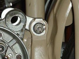
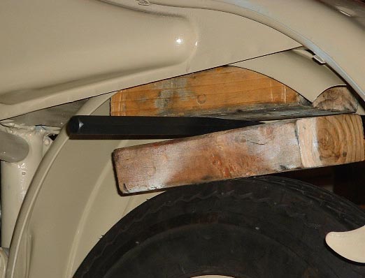
Once you think you have the right spline, check to make sure that you will be able to get the forward link bearing and pin installed. With the link in position you may notice that the holes don't quite line up. You'll have to temprarily torque the torsion arm forward a little against the torsion of the bar to line up the holes. The picture shows how I did it, with a couple of 2x4 woods between the tyre and underside of the fender, then start driving a wedge in between them which will gradually push the tyre down, effectively pulling the motor lugs rearward until they exactly line the holes up.
Now for final assembly.
I think that if you decide to change the spline adjustment later then all you have to do is remove the right hand t-bar circlip, tap out the bar from right to left, rotate as necessary and re-install. If you have to compress the motor bumpstop, just get out the ole' wedge 'n' woods and go at it.
Lambretta toolkit
This is a good travel kit. For daily commuting you may not want to carry all of it, then again if you ride all the time you probably should. Send suggestions if you notice something missing or useless in this list.
Subject: Mounting tubes into tyres onto Lambretta rims onto Lambretta hubs.
Subject:You want your scooter bodywork to go together right.
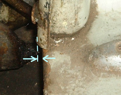
This is about what to look at while assembling LD or LI bodywork onto the rolling chassis, typically after a re-paint, so that the bodywork fits well and the parts don't rub the paint off of each other. Attention to this issue will account for the important difference between a well and a poorly assembled Lambretta. These points of fit between the various body parts should be resolved and adjusted as necessary before any prep or painting is done, so that when you get back your shiny painted parts ready to assemble, you'll know that they are going to fit. Picture 1 shows the rear edge of the legshield too far rearwards in relation to the rear edge of the sidepanel channel.
So in a nutshell: first the footboards locate according to where the panels go, then the legshield locates according to where the footboards go, giving everything a little space in between.
Now let's go. There are a number of separate body parts which fasten onto the frame. They're each supposed to mount up with a little distance between them and the part next to them so they don't rub against one another. On LI type Lambrettas, there are little rubber washers between the frame and footboards and between the frame and the floor portion of the legshield. On LD type Lambrettas there are no rubber washers. All of the different body parts are slightly adjustable as to their exact location on the frame EXCEPT FOR THE SIDEPANELS. Since you can't adjust the sidepanels to the rest of the bodywork, you have to adjust the rest of the bodywork to the sidepanels. This is most obvious on LDs and Series I/IIs because of how the sidepanels curve closely downwards around the rear end of the footboards.
1.First let's look at the various struts, that is the rear footboard supports, the main crossmembers which hold the centerstand on LIs or which hold up the front of the footboards on LDs, and the forward legshield supports. On the LD forward legshield supports, make sure that all the 4mm threaded holes are in good shape. You can do a pretty good job at ascertaining how straight everything is by using two different approaches
.
First, with all bodywork removed and the bike standing there as a rolling frame, or with a bare frame on blocks, view the bike from the front so that you can sight back along all the crossmembers and see if ther're parallel with one another and perpendicular to the forktube of the frame. Adjust as necessary. Then view the bike from above and see if all the crossmembers are again parallel with one another and perpendicular to the frame. Adjust as necessary.
The second approach is to use a yardstick or whatever to see if you can identify a straight line along all the points that the footboards and legshield will mount to, so when viewed from the side it will be evident as to whether or not the surfaces of the legshield and footboards will be in the same plane.
Sometimes the feet of the rear footboard supports get bent downwards and this can make the footboard hang low in back. Bend it upwards till it's horizontal and parallel to the whole floor surface of the scoot.
Sometimes the whole rear footboard support can get bent inwards or outwards, causing the same problem. But also and more so this causes the footboard to swing inwards or outwards at the rear. This will be evidenced by a crooked or unparallel joint to the legshield at footboard front, and especially on LDs by the footboard not being parallel to the legshield along the outer skirt surface. It will also affect the gap between the footboard and sidepanel.
Sometimes the whole rear footboard support can get bent forwards or rearwards. This will be evidenced by the fact that the footboard mounting studs won't easily drop into their holes and rather the footboard has to be forced in and out of place. There should be a distance of approx. 11 5/8'' to 11 11/16'' between the front and rear footboard supports. Knock the rear strut forward or rearwards till the foorboard fits, then try the sidepanel for clearance with the footboard. In unusual circumstances, both front and rear footboard struts may have to move forward to clear the panel, but this would be rare.
Sometimes the main crossmembers get twisted or bent up, especially on LIs. Since the footboard and legshield both rest and meet on this piece, it must be flat or the sheetmetal won't meet up co-planar. And while I'm at it, on LIs make sure that your stand mounting holes aren't mushroomed out, if they are then fix 'em and use stand re-inforcements when you mount your stand. Regarding stand reinforcements, denfinately call WCLW and ask to speak with Vince at 619 229 0201.
2. Put the footboards loosely on the frame. For SI/II and if you haven't done so, attach the righthand footboard support to the rearside of its mount on the frame and also put on loosely the footboard strips or use 5mm bolts to locate the footboards to the frame. Now put sidepanel beading on the frame, install the panel latches and put the panels on the scooter. You should have a minimum of 1/16'' clearance between the rear end of the footboards and the sidepanel where it curves down around the rear end of the footboard. That's where the footboards go. At the front end of the footboards you'll want about 1/8'' between them and the legshield. You may want to mark the location of the front of the footboards somehow for reference when placing the legshield.
3. Take off the sidepanels and footboards off and install the legshield. Now though it's easier said than done, I'm talking, not doing, so it's pretty easy for me. Fasten the legshield down with that 1/8'' clearance from where the footboards were supposed to go. To accomplish this, basically you fasten the top of the legshield first with the two little bolts from the front, usually so that it just clears below the chrome lock ring at the top of the fork column. Then you push, pull or lever the legshield forward from the rear edge till it's where you want it, getting it the same on both sides, then fasten it to the frame to keep it there. Now put the footboards and panels back on and see if everything clears. Once you have a tentative location for the legshield, fasten the horncasting on to make sure that it lines up with all its fastening holes. LI owners, try the footboard bridgepiece too with its rubber pieces.
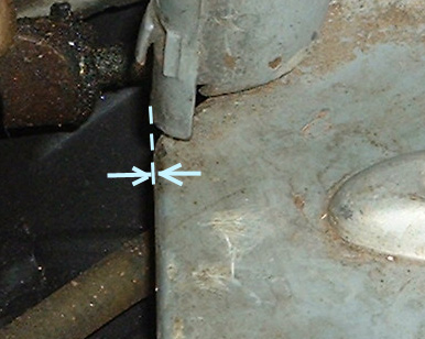
The pictures below offer a tentative indication as to whether or not the legshield is in the right place. They show the same detail of the right side of two different scooters, at the rear edge of the legshield floor where it would meet the footboards.
Picture 2 shows the rear edge of the legshield more properly related to the sidepanel channel.
1,2,3, it's so easy, like taking candy, from a baby...
 Here's an addition. If you need to move the crossmembers or footboard supports on an LD, You can do it with a piece of 3/4'' steel bar about 2 feet long as a lever. Slide it inside them and have a go at it. Usually you'll have to round-file out some chunk of paint or weld from the inside of the tube. For the footboard supports you'll have to lie the bike down on it's side
top
'o'
page
jonbretta >
home
page
Subject: Jetting.
If you want to learn about jetting, this is a great site so click on this: http://www.motocross.com/motoprof/moto/mcycle/carb101/carb
Subject: installing LD crankshaft seals.
This dissertation is based around the MK II and III seal, part # 11110351, size 31x47x7 mm, 3 required, in Mk II and III LDs. The techniques described will probably facilitate any Lambretta seal installation, though these particular seals can be tough to do well by lesser means.
First, you need a tool to install the seals with. You can use a half-inch drive, 1 1/4" socket, or you can make "the tool". The tool is a piece of pipe/tubing say 3-6"long, with an outside diameter of 1.7 inches (maybe 1.75 inches max) and an inside diamenter of 1.4 inches minimum. The greater the wall thickness within those dimensions the better. The business end must be cut squarely and de-burred. Make sure that the inside of the pipe is cleaned of dirt, metal shavings, etc. so that stuff doesn't fall into your job while doing it. The goal for the tool is to fit into the open side of the seal after removing the seal spring. To remove the seal spring, lie the seal down, open side up. Bend the inner lip of the seal inwards towards the center of the seal and hold it there.With your other hand, lift, don't stretch, the spring up and over the folded in lip of the seal, then off from around the rest of the lip.
Set it aside.
Next, use the tool to install the seals. Lambretta crank seals install with the open side facing the crank Grease the seal to make it go in easier. A press of some sort is better than hammering the seal in, especially with the more tight fitting
seals and bearings, as those sometimes require real cro-magnon bash ratings to complete and we've found better ways to do things right? Hammering can work, but just how many spare LD crank seals do you have.
If you're hammering, put the crankcase or flange on the floor or a solid bench. Put the seal in place. Push-start it in with your fingers, all the way around. Put the tool into the seal recess, it should fit right into the seal. Then just press
(or hammer) the seal home. Lay the spring on the seal, fold a side of the lip inward, and put, don't stretch, the spring back into place. grease the inner lip for the shaft upon it's installation, and you're there.
Mk III drive side seals are installed in a bearing retainer plate, like LIs. Remove the old seal by bashing it out of the plate with a big socket, seal side down, plate resting on a couple of 2x4s or vice jaws spread 2 inches apart. Ideally,
put the seal plate vertically in an aluminum padded vice, holding it by one section of the edge. With a hammer and a rounded tip driver of some sort, try to, from the rear of the plate through the seal hole, drive the little seal keeping
inwards-bent edge of the lip back out to allow the new seal to go back in. Whatever amount of that edge can't be knocked fully back out of the way must be fully ground away until that entrance for the seal is flush with the whole inside of the seal's resting place. Don't leave burring around that outside edge that can cut up the seal when you start it.
Remove spring, grease and install seal, open side towards crank. Now put the seal plate back in the vice and peen that lip back down around and over the edge of the seal. I hear that they stay in anyway but why find out. Replace spring. Install new o-ring (part # 11110342) around the bearing. Use new bolts and lock washers, as you really don't want to break one of those old bolts off in the crankcase.
Subject: Holding nuts into hard-to reach places. Case in point: bolting on the spare wheel carrier on a Mk III.
Us short-fingered people develop bigger brains in the course of coping with our anatomical inadequacies. Case in point: hard to reach destinations for the washer/nut combination. You know the place. It's the two rearmost holes way down at the back and bottom of the Mk III toolbox. So take a foot or so of wire, put it through the hole from the outside and pull it through (not all the way; remember the part about the bigger brain?). Slide on the washer and nut over the end you pulled through, the wire will guide them and your finger(s) right up to the hole where it will now be alot easier to hold them in just the right place for the bolt. Once they're in place, pull the wire out and gently screw in the bolt. Did I forget to mention that you already loosely bolted on the carrier with the forward two bolts so you don't have to be holding it at the same time as you do the wire trick with the back fasteners? Amen. This also may work well for LI rear seat /TV seat latch bolts. (I've since tried it, it does.)
Subject: lightbulb blowing on A.C. lighting system Lambrettas.
It's probably your stator, or more exactly the lighting coil thereon. If you think about it there's really not much to those systems. A magneto, some wires and some bulbs. That's it. What else could it be? This was my thought process as I tried to figure out why my Series II was having this problem. It's an occasionally encountered problem with A.C. Lambrettas, though usually on 6-poles. One popular repair is to tell the customer: 'Sorry, we don't know what the hell's going on here so we put in a bunch of 12 volt bulbs, try that for a while, see ya' Another popular cure is to install a 6v. 'zener' or 'clipper' diode (if you can find one). I'm told it works well, as it grounds off voltage in excess of 6 or whatever its cutoff is. Not wanting to have to hunt one down and unwilling to send myself down-the-road in the dark with some hope-this-works lighting scheme,
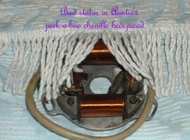 I opted for actually repairing the problem. So I got another stator and swapped it in; and as it turns out, BINGO! Before I swapped, I put in all new bulbs, started the bike and warmed it up till it would sit and idle happily for an indeterminate length of time.
Then I got an AC voltmeter, turned on the lights, and tested the brown wire output while everything was on and hooked up. I was getting 5 - 5.5 volts at a nice 'taillight' IDLE! Well what do you think THAT stator's going to put out at 3 or 4 thousand RPM? Too much. So then I changed stators and took another reading and read about 3.5 volts at the same idle, which is about what you want to see from the brown wire. That's more like it, so I went out over the next few days on some long high speed stretches, lights on, and they were all still on and doing fine when I finished. End of problem. I think you can buy new 6-pole AC lighting coils but for 4-poles you may have to rewind yours. It's not hard, just time-consuming, but it beats not being able to ride just because the sun went down and your lights blew up by about the time you shifted into third.
I opted for actually repairing the problem. So I got another stator and swapped it in; and as it turns out, BINGO! Before I swapped, I put in all new bulbs, started the bike and warmed it up till it would sit and idle happily for an indeterminate length of time.
Then I got an AC voltmeter, turned on the lights, and tested the brown wire output while everything was on and hooked up. I was getting 5 - 5.5 volts at a nice 'taillight' IDLE! Well what do you think THAT stator's going to put out at 3 or 4 thousand RPM? Too much. So then I changed stators and took another reading and read about 3.5 volts at the same idle, which is about what you want to see from the brown wire. That's more like it, so I went out over the next few days on some long high speed stretches, lights on, and they were all still on and doing fine when I finished. End of problem. I think you can buy new 6-pole AC lighting coils but for 4-poles you may have to rewind yours. It's not hard, just time-consuming, but it beats not being able to ride just because the sun went down and your lights blew up by about the time you shifted into third.
By the way, 'taillight idle' is the concept, again for 6VAC bikes, of setting your idle speed up high enough so that your taillight is adaquately visable when idleing (at a stop light for instance) at night. Safety First.
Subject:Converting MK I and early MKII tailshaft drive bevel bearings to the later, better layout.
OK so of course you just happen to be rebuilding the tailshaft of your MK I, MK II 150 engine no. 161051 and earlier, or MK II 125 engine no. 323680 and earlier. Of course. Those units used two of the same bearing, the RIV EL20, Innocenti part no. 07330207, which is available under the common bearing stocklist bearing no. 1604, to carry the tailshaft pinion driving gear. After those unit no.'s the design was changed for the better by using a more robust bearing in the rearward location closest to the job at hand, which is to turn the big bevel driven gear on the axle and make the scooter go, if that's what you can think of these scooters as doing. This post-mod bearing is Innocenti part no. 19030033, common bearing stocklist no. 6004. It's the same bearing used in LIs to carry the mainshaft gear cluster in the endplate. Apparently the Innocenti folks saw enough of what I've also seen, wiped out EL20s in that rear position. With the recent introduction of the XP porting scheme and its additional 1-2 hp output, the upgrade is even more prudent. The 6004 is wider and has bigger balls. There's a tubular spacer between the two bearings and the pre-mod type has to be shortened to 21mm to accomodate the wider bearing, making sure to chamfer inside and out the newly turned end just like it was to start with. Or you can just buy the post-mod spacer if you can find one. Oil and tap in the new seal, Part #07330213, 20x35x10, open side facing forward toward the transmission, about half way into the spacer; it's not terribly crucial. It doesn't have to be exactly 10mm. 7,8,9,10,11,12 would do. Single or double lip. Re-assemble bearing/bevel group and put it back into the tailshaft. Make sure the bevel group shim is still in the tailshaft before you re-install. Your tailshaft is now all post-modded up.
|
top 'o' page |
jonbretta home page | >
Subject: Soldering on a small ball end for the throttle or choke cable.
Buy a foot of 1/16" brass tubing at the hobby or hardware store; call first to confirm their selection of little hobby-grade brass.
Buy some Tinners Fluid from the plumbers store, and some silver braise or silver solder from the hardware/auto parts/hobby store. You also need a propane or some little torch.
Cut about a 3/32" long piece of the brass and square and clean up the cut end.
Make sure to hook up the other end of the cable with the throttle or choke in the closed position for accurate location of the ball end when you solder it into position.
Slide your little brass piece onto the cable and mock it up in position at the carb or choke plunger. Make sure to close the cable adjuster on the carburetor all the way down, and then back out about 1/8" to allow for final adjustment as necessary.
When positioned, make a little mark right next to the tube with a fine black marker (Sharpie) so you then know where to solder it.
Bring the cable back out of its location. Making sure to keep the brass end exactly where it will go, clip off your excess new cable length a little bit further out than the end of the brass. Spread out the strands of this extra little length of cable so that they make sort of a cone or funnel shaped fan as wide or a little wider than the O.D. of the brass. This will prevent the brass from coming off, now and after you've soldered it.
Now it's time to solder. Put the cable so you have room to comfortably AND SAFELY solder it. Clamp or somehow hold the cable so that it is horizontal and pointing outwards away from the bike and AWAY FROM THE GAS TANK. As necessary make sure that the brass is slid back to exactly where you marked it to go.
Drip some tinners fluid onto your brass and cable so that it runs all through the joint. Heat the work with the torch and then while heating, feed in the solder. Don't breath the smoke. The first time, the solder may not spread, so wipe off any black residue on the work and re-apply tinners fluid and re-solder the work. Don't go overboard with flame size, not much is needed. This time you shoild get a nice little ball of solder over the brass and cable. Make it so that it's a nice chubby size, and that it still fits through the cable adjuster or into the choke plunger. You might need to file down a side of it to fit. There you go.
Subject: Fixing stripped choke threads on your Lambretta carburetor.
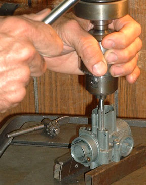
This job takes a lathe, good condition drill press, and a hydraulic press to do well, and a 9mm x 1.0 tap to do at all, so get those things or take the job to someone who has them and will do the job for you. I currently have access to them so I might do it for you for a fee, probably about $40.00. Part 1: Drilling out the bad threads and beyond.
Part 2: Make the insert.
Part 3: Prepare and install the insert.
Part 4: Tapping and finishing the insert; whew!
Now I've done this a few times on SH carbs so this procedure will be for them. I'm sure that one would use the same procedure on MA/MB carbs as well, making adjustments if needed regarding drill diameter, insert depth, or anything else.
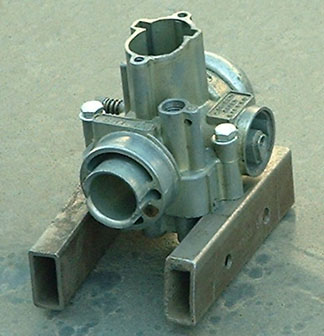
Disassemble the carb completely.Get two pieces of 1'' square or rectangular tubing, (cut a longer one in half!) or any pair of things that are exactly the same height and a minimum of about 4 inches long. Drill and tap to 5 mm a hole along close to the edge and about half way along the length of each of the two pieces. Clean off any drill or tap welting around the holes. Mount the carb on these blocks using the float bowl screws or M5x30 bolts with flat washers. Set this on the table of your Drill Press.
Set the drill press for about 300 r.p.m. I suggest drilling out the choke bore in two stages in order to minimize the chance of the bit grabbing the part or of the bit not starting concentrically to the bore. First use an 11/16 bit. chuck the bit tightly, then set the depth stop for .840" from the top of the bore, +/- .015''. That depth stops just short of the horizontal bore for choke air intake, which can be seen from the front of the carb. Set the depth by marking the depth on the outside of the part of the carb you're drilling. Then set it on the press just off to the side of the bit and lower the bit to the mark and tighten your depth stop. Test-lower the bit outside of the carb to see if it stops where your mark is. OK, so drill it out, holding the carb firmly with one hand while you drill with the other. Feed slowly, and clear it frequently 'til you're there. Dump the junk out of the carb.
Now put in a 25/64 bit, which equates to .394''. Double-check your depth; you'll probably need to reset for the new bit (the bits are new, aren't they?). Drill out to this final size and depth. Blow out and clean out the carb.
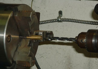
Assuming that you don't have some lying around, go buy some 7/16 brass round rod, 1/2 inch if you can't find the smaller. Cut a few 1 1/2'' pieces in case you screw one up. Put one in the lathe and get an 8mm drill bit and drill all the way through that puppy. (NOTE: a 5/16 bit didn't work for me even though they're supposedly the same as an 8mm, I had to drill the insert out later with an 8mm for the choke plunger to fit into the carb.) If it went off crooked through the brass, try another one and go slower or get another lathe. If it drilled true down the whole length of the rod then you're in. Now set up a bit to cut down the outside diameter of the rod. Hold the piece by about 1/2 inch, thereby leaving an inch available to be turned down. You're going to turn about .900'' down to final diameter, so that leaves you with about .100'' safety margin to avoid hitting the chuck with your tool (Did I mention SAFETY GLASSES?). That 25/64 bit is around .394'' in diameter, so when you get .010 or .020 close to arriving at that diameter, stop the lathe, back away the tool and try to fit the carb onto the insert. You're looking for a light snug fit, and you should be able to push the carb on a small part of the way by hand before it becomes too tight to continue. Various factors make it too difficult to specify here a certain dimension, so it's a judgment call. If you think that the piece will press in the rest of the way without being too tight and splitting the carb out, then you're done on the lathe.
Get a hammer and a sharp small chisel. put the 8mm drill bit in the insert for support and lie the turned-down part of the insert on an anvil with the unturned part hanging off the edge so it allows the turned part to lie flat. With the tools, put some light burrs lengthwise here and there around the insert to give it grip when it's pressed in. Don't hit it too hard or you'll expand the diameter of the insert.
Get some bearing lock goo such as Loctite 660 or some other stuff like that's designed to fit bearings which have become worn or loose in their landings. Smear it around on the insert. Install the insert into the carb. tap in lightly with a hammer 'til you're sure that it's going in straight, then continue installation with a press or maybe in a big vice. If the turned length of the insert is greater then the depth drilled into the carb such as will be the case by having followed the dimensions suggested above, then the insert will stop in the carb with just a 16th or so of the turned length still showing at the top. Put the job away for as long as it takes for the bearing lock goo to dry.
Now clean it up real well and try to drop your choke plunger down the hole. if it goes all the way down then you're done. If not, put the 8mm bit back in the drill press and run the drill all the way down until it just starts to touch the bottom of the bore, where the choke jet sticks up through. Withdraw drill, clean carb, try plunger. You may need to file the new bore out with a fine round file,run the 8mm drill in it some more, finely sand your plunger, or get one that's worn smaller. The plunger should slide all the way down by itself so you can see it blocking the air intake hole in the front. Then while it's in there, screw in the choke jet from below. You should see the plunger slowly rise as the jet screws home and lifts the plunger.
Put carb in a PADDED vice so that you can hacksaw off most of the excess insert, but leave it about 1/8 inch taller than the casting around it. now put your 9mm tap tightened into the drill press. Put the carb under it. While applying slight pressure with the drill press of the tap into the insert, HAND TURN (no motor) the chuck with the tap in it into the insert and start cutting threads.
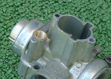 Using the drill press will guarantee that your threads are straight in the carb. Tap down about 5/16 inch deep, clearing the tap frequently for nice clean threads. Now machine the insert down to final level, flush with the carb. Do this preferably by milling it, or if not, then put it in a vice, hacksaw it off very close to flush, and finish with a file. Next, run the tap back through your new threads to clean up the beginning where you just milled or filed. Try the plunger again, if it goes, you're done. Remove blocks, clean, re-build, and install carb.
Subject: Converting LD brake light to ''pink wire'' power supply.
Building a ''PINK WIRE'' brake light system into an LD |
|
|---|---|
|
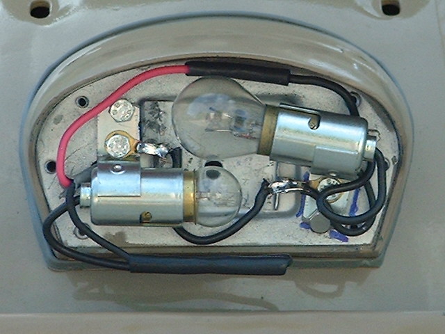
Apparently, most of the LDs exported to the U.S.A. had non-battery lighting systems equipped with brake light, with the obvious exception being the AVV (electric start) models which did use a rectifier and batteries to power everything. But other than the AVVs, which I haven't seen from the rear either for that matter, LD brake lights are usually pretty inadequate. In about 1961 or so on the current LI model Innocenti came out with the last version of their 4-pole generator which featured a separate stator output for the brake light. This ''PINK WIRE'' scheme provided the brightest brake light yet with operation independent of the other lights. Certain parts were needed to achieve this system. They were an un-grounded low tension ignition coil with a pink wire as one of the outputs of the magneto, a 'momentary-on' grounding type brake light switch, and a new tail light enclosure and bulb complement which came to be thought of as the 'post-mod' type Series II tail light. This new dual filament 6 volt bayonet mount tail light bulb featured a 21 watt brake light filament, which balanced with the new pink wire output, as well as a 5w. running light filament.
|
|
|
Note to LI Series I and pre-mod Series II owners: Yes, you to can retrofit this modification. Buy the Post-mod Series II brake light switch, part # 19181390, and buy or somehow get a post-mod Series II tail light housing, part # 19083110, because it holds the post-mod Series II C.E.V. dual filament bayonet socket/reflector and lens necessary for doing this conversion on your Lambretta. The stator work and brakelight circuit wiring diagram is the same as is below described for the LD. Update: October 2004; ScootRS has a reproduction post-mod SII taillight complete for $24.00! |
|
|
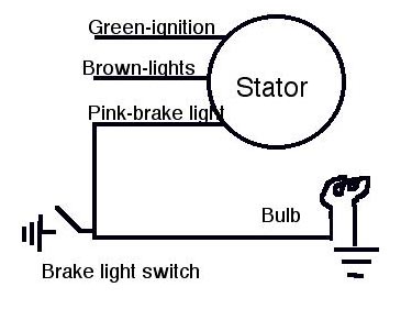
First let's look at how the pink wire system works. there are three points in the circuit to hook together, the stator brake light (pink wire) output, the grounding brake light switch, and the brake light bulb. Physically it doesn't matter how they all get connected to each other as long as they do. but I'll here describe a layout which illustrates how it functions A wire goes from the stator pink output to the brake light switch, and then from that same point on the switch back to the brake light bulb. That's it. That's all there is to the wiring diagram. Now the stator pink wire is actually one end of the stator's ignition coil. In previous Lambrettas this end of the coil was grounded to complete the ignition circuit. On the pink wire Lambretta this grounded end of the coil was lifted, and run out of the magneto as the pink wire. but still needed to ground somewhere to run the ignition. So when you're riding (and not braking) the pink wire current goes to the brake light switch and grounds there, because the switch is being held 'on' by the pedal, thus completing the connection to ground. When you step on the brake pedal, it turns the switch off and breaks that ground, so the ignition ground has to go back to the brake light bulb and ground through it, thus completing ignition and lighting the brake light. The brake bulb is a resistor, so current will only go through it if forced to do so by removing the non-resistor easy passage to ground when you open the brake light switch. |
 |
| The BIG DRAWBACK to the 4-pole pink wire system is that if your brake light bulb burns out or becomes disconnected somehow, then when you step on the brake pedal, your ignition will cut out, and when you lift off the pedal your ignition will come back on. I choose to just carry a spare bulb and screwdriver for the sake of having a much better/safer brake light.If it does burn out, you know about it immediatly 'cause your ignition starts cutting out wen u brake. | |
| Step 1: wiring up the stator.
Remove the stator from the scooter so that you can work on it in a clean well-lit controlled situation.
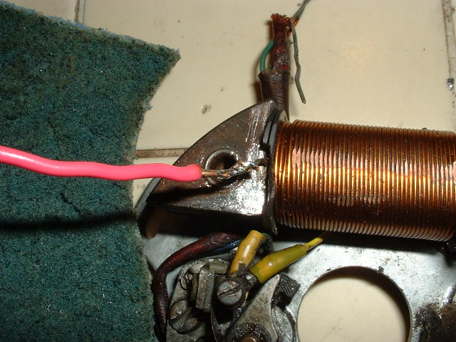
Get about a 6 inch piece of copper wire like the coils are wound from, the exact guage is unimportant. Wrap-connect it to the newly lifted end of the coil, keeping the connection as narrow and tight as possible. Solder them together. Make continual inspection of the wire where it comes out of the coil to make sure that it stays lifted away from and free of contact with the core to which it used to be soldered. If you've been having starting problems and have decided to rewind your ignition coil, this would be the perfect time to just leave a long lead for the pink wire at the beginning of your rewind, thereby saving the splice work. |
|
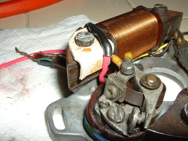 This second pic shows the plastic guard/cushion/insulator which I made of tupperware, plastic water bottle, kid's unbreakable toy kind of stuff. Bend it tightly to wrap over the edge of the core. Drill a hole in it so the the coil mount screw will hold it in place. Make sure that it fits right up tight against the fibre coil insulating plate so as to keep the new wire and solder job lifted Up, Up, and Away from the core and certain short-circuit cataclysm. This doesn't involve catacism.
Feed the new wire over the newly padded corner of the core and down under the coil along with the other wires, out to the junction. Cut the new wire to length and strip to mimic the ignition and lighting wires. If you have that red wire that used to be in the third spot that you'll now be using for the pink wire, fold it back and insulate it from contact with anything, and locate it safe from the whirling flywheel. |
|
| Step 2: switch and bracket.
The switch is a heavy duty SPST (single-pole, single-throw) MOMENTARY (ON) toggle switch. |
|
|
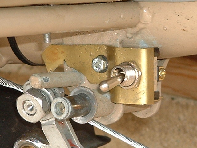
Regarding the bracket, it's a flat metal strip about 1'' wide and of sufficient stiffness to hold the switch in place. I used 1/16'' brass plate.
2. You'll probably need to bend in a jog a little rearwards of the switch to outset it close enough to the pedal for the pedal to operate the toggle. I'm guessing at about 1/4'' outset towards the drive side. 3. Put it up in place, You'll probably need to cut some notches along the bottom edge of the bracket to clear the pedal pivot and pedal stop posts. Once you get the bracket where you want it so that the pedal in its fully returned position holds the switch toggle up, hold it in position and mark a spot where you want to drill for the mounting bolt. Take the bracket out, drill a 5mm hole in it, put it back in position and mark through the hole onto the pedal post bracket to indicate where to drill and tap for the 5mm bolt. Do tlhe drill and tap. Put it together with a short 5mm bolt and lock washer, you're there. This bolt also provides an nifty ground point for your switch ground wire. |
|
|
Step 3: Bulb. For this Euro model tail light I removed the festoon bulb holders and flattened down the mounting tabs. I went to the auto parts store and bought a generic dual-filament bulb holder and pop-riveted it in, wired it up and put in the standard pink-wire system bulb in, that being the dual filament bayonet style bulb 6v. 21/5w., commonly known as #1154. That completes the set-up, I thought,,, BUT....... Wait!! Stop, I was Wrong..........I tested the 1154 bulb and it worked great except for one thing- when I use the brake pedal at any sort of lower revs, the ignition starts to cut out and eventually dies. The brake light works like it's supposed to and everything, it just craps out the ignition. If I hold the revs up, it doesn't die. Here's my hypothesis... The LD generator doesn't put out the current that the LI system does, and I think that the LD flywheel magnets aren't as strong as the LI ones. So when I try to drive the #1154 bulb's 21w. brake light filament with the LD ignition coil/pink wire, the coil isn't developing enough juice to run both things, because the LD magnets don't generate as much current in the coil as the more buff LI ones do. The LI and LD low tension coils aren't so dissimilar, but I think that the flywheel magnets are. So what's the answer ? Lessen the demand on the coil.
I found a bulb. It's a single filament bayonet bulb,
#87,
rated 6v. 15cp (candlepower). The numbered values of cp and watts seem to oftentimes be Really similar, so I'm guessing at ol' #87 being a 15 or so watt bulb, the perfectish bulb for the LD pinkwire system. I hooked it up, took it for an extensive test run and BINGO, real good solid brake light and no ignition kill, no sluggish display of nebulous brake light, no dimming of head and tail light when brake light is applied, just BANG!, BRAKE LIGHT!.
|
|
| Note to LI Series I and pre-mod Series II owners: Your tail light bulb will be the single 6volt, 21/5 watt dual filament bayonet bulb, same as any Series III or post-mod Series II, just as is designed for in the post-mod taillight housing and reflector you've procured for this conversion. | |
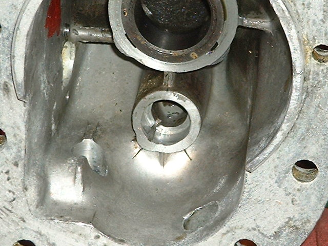
Replacing LD secondary shaft bushing
| About half of them seem to come out or loose, here's how to replace them, in most cases. This method will apply to cases where the aluminum landing of the case has not broken away or cracked or wallowed out excessively.The fit of the shaft in the bushing usually feels a little loose, and probably is, as the brass must wear from use. If it's real bad then you should find or make another bushing. In such event keep in mind that the tighter the fit into the case, the more stress there will be on the surrounding aluminum, and the more the bushing will compress when pressed or tapped in, and that will change the fit with the shaft. | |
| Clean the aluminum and bushing really well, them maybe even break the surfaces with sandpaper to expose good clean new metal. |
|
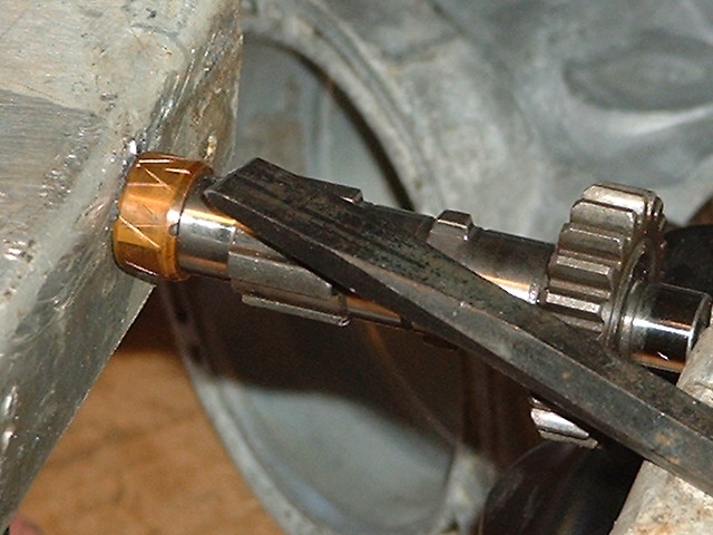
| Now take the bushing and put it over the small end of the secondary shaft and in a padded vise like in the pictures. Take a hammer and sharp chisel and make a crosshatch pattern like ''in the picture''. Don't hit real hard though, too much force can expand the bushing too big to fit the case and too loose for the shaft. The edges of each little cut stand up higher than the surface of the bushing and make it fatter and provide a grippy knurled surface to bite into the aluminum. |
|
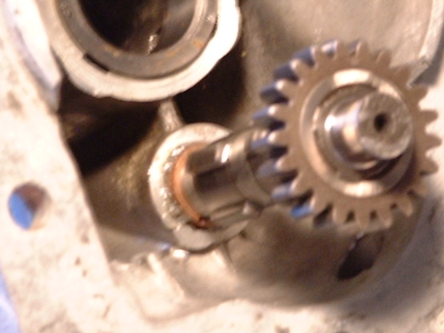
| Try the part in the hole. You should be able to push it in almost half way with your fingers before it gets too tight to proceed. If it's still too loose, knurl it more with the chisel. Once you like how it's feeling in the hole. Get some Loctite 660, Pressloc, or some other bearing seating goo. Rub a film of it into the hole surface, making sure not to fill or clog the oil passage molded longitudinally into the hole, shown in the top picture. Then rub a coating onto the bushing, but wipe off a narrow strip which you will line up with the oil passage in the hole so you don't clog it. Put the bushing into the hole as far as you can push it, then tap it in the rest of the way with the secondary shaft, like in the fuzzy, out of focus picture to the right, sorry. Use a woodblock or something to pad the shaft from the hammer so you don't mushroom or nick it. |
|
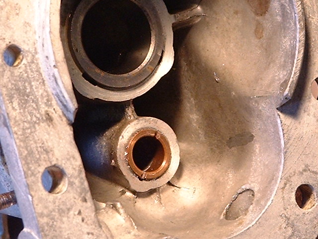
| Tap it all the way in until you feel it come to a stop, even when it's all the way in it sticks out a little from the surrounding aluminum. Wipe away the excess goo from around the outside, and swab out the excess from the inside. Blow through or somehow confirm that the lube passage stayed clear. Let it set for a day before use. |
|
My home made LD tools.
1. Flywheel holder. For all Lambrettas.
2. Flywheel puller. I didn't make this one, I bought it. It's the same as for Italian LI,TV,SX.
3. Rear hub puller. One set of holes is for LD, another set is for LI.
4. LD magneto flange puller. Screws onto flange after removing stator, big middle screw pushes on crankshaft.
5. LD clutch compressor. Compresses clutch against springs so that you can remove the clutch retaining circlip.
6. LD clutch bell puller. Made from a clutch metal (driving) disc, held within the bell by placing the circlip back in over it,
big middle screw pushes on mainshaft.
7. LD clutch hub holder. Machined from 1 1/2'' diameter steel rod. Keeps clutch from turning while you R&R clutch bell nut.
8. LD clutch collar holder. Made from a clutch cork (driven) disc. Locks collar with bell while you R&R clutch collar nut. One of those welded-on tangs actually should be a few inches long to brace against the muffler mounting stud lug on the front of the crankcase.
9. LD crankshaft seal set. Its use is described in the tech topix page, crank seal procedure article.
For a more informative and practical description about any of the items, email me.
|
top 'o' page |
jonbretta home page |
 This D headllight bucket has that quintessential Innocenti 50s grey/green color perfect condition NewOldStock paint on it and before I had to give it back I went to the paint store to identify the color. Here are some good candidates, all by Dupont and available as single stage paint, either as their Centauri acrylic enamel or as one of their more expensive urethanes. This photograph looks more green than the actual part did, probably because I took the pic with my camera by FUJI, a company known for its products greenitude.
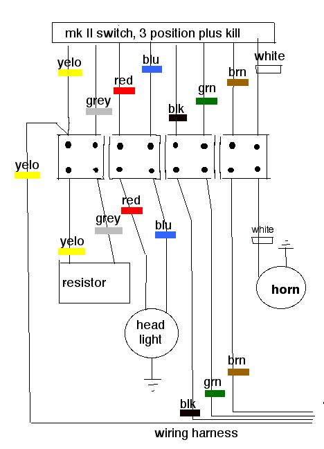